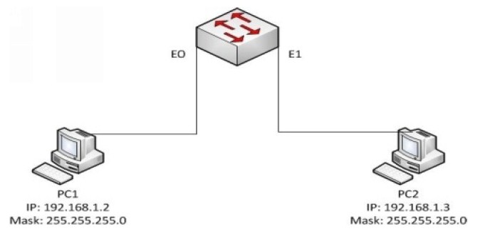
In the below diagram, PC1 pings PC2. The IP packet is encapsulated using an ethernet
frame and is sent to the E0 interface on the switch. The frame has the source mac-address
as the mac-address of PC1 and the destination mac-address as PC2
The switch looks into the source mac-address inside the frame. If it is unavailable on the
cam table of the switch, the switch adds the information in the table. The switch then
looks into the destination mac-address, and checks for the corresponding information in
the cam table. If unavailable, the switch uses a technique called flooding, where the frame
is sent out to all ports. When PC2 responds, the destination mac-address of PC2 is added
to the corresponding port and the cam table updated. For subsequent packets, the frame is
not flooded, but sent directly to E1 since, the information is already available in the cam
table.