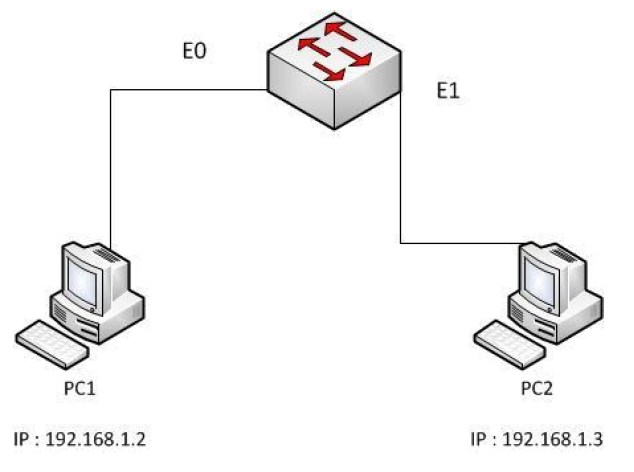
“In the above diagram, PC1 pings PC2. An IP header with the source and destination IP
address as 192.168.1.2 and 192.168.1.3 is created. PC1 sends an ARP request frame to
find the mac-address of PC2. This is required to construct the ethernet frame to
encapsulate the IP packet. After the mac-address of PC2 is received, the frame is
constructed and the IP packet encapsulated. The frame is sent to the switch and is received
on port on E0. The switch looks into the destination mac-address in the frame, which is
PC2’s mac-address and checks if the entry is available in it’s mac-address table. If yes, the
frame is forwarded to the port on which PC2 is connected. If unavailable, the switch
floods the frame to all ports. After PC2, receives the frame, it looks into the destination
mac-address to check if the frame is intended for itself. Once verified, the destination IP
address is verified with it’s own IP address. As it is a match, the ping packet is processed
and the response to the ping packet created. The response packet would contain the source
IP address as 192.168.1.3 and the destination IP address as 192.168.1.2, and a new frame
would be created with the source and destination mac-address as PC2 and PC1
respectively.”