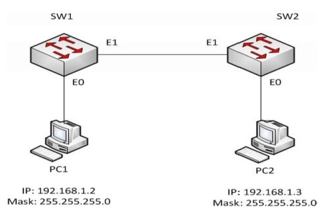
In the above diagram, PC1 and PC2 are connected to respective ports on the switch as
shown below. The switches are connected to each other using the E1 ports on the
respective switches. When PC1 pings PC2, an ARP request packet is generated, for
identifying the mac-address of PC2. The ARP request packet is a broadcast packet, which
is broadcasted to all ports on SW1. The ARP packet would be sent through the E1
interface on SW1, reach the E1 interface on SW2 and eventually reach PC2. PC2 would
respond with it’s mac-address to PC1. Now on SW2, the mac-address of PC1 is added to
the E1 interface on SW2, as it had received the ARP request through the interface, which
had the source mac-address as that of PC1. This information would be updated in the cam
table of SW1. The ARP reply would be sent out through E1 on SW2 and E1 on SW1 and
eventually would reach PC1. The next time PC1 pings PC2, the cam table of the switch
would list the mac-address of PC1 on E1 on SW1. All packets would be sent to E1 on
SW1, which would then be forwarded out to SW2.